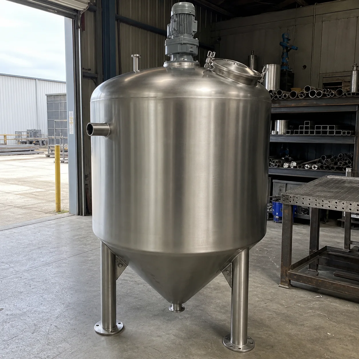
1. Define the process duty before the geometry
State usable and total volume separately. Include product density, viscosity, solids, operating temperature, pressure or vacuum, filling and emptying pattern, cleaning method and any hygienic requirement.
These inputs affect shell thickness, head form, freeboard, mixer duty, nozzle sizing, heat-transfer surface and support loads. If the duty is not clear, the lowest initial price can hide the largest project risk.
2. Make the vessel geometry and joints explicit
Define the top and bottom geometry: flat, dished, torispherical, conical or another project-specific form. At a butt-welded head-to-shell joint, the mating diameters, edge preparation and tolerances must form a continuous joint suitable for the agreed welding procedure; a head should not appear nested inside the shell unless a different engineered joint is intentionally specified.
State the support arrangement, floor condition, anchor requirements, lifting points and access. Support feet and anchor plates should follow the calculated loads and the real foundation detail rather than decorative or unnecessary adjustable parts.
3. Control material, welding and post-weld condition
Specify the required stainless grade and certificate level. Define the applicable welding procedure, welder qualification, joint access, visual acceptance and any NDT or pressure/leak test required by the project.
Where corrosion resistance or hygiene matters, define cleaning, pickling and passivation after fabrication. Heat tint and embedded contamination should not be accepted merely because the weld bead is structurally complete. If a surface roughness target is important, state the measurable Ra requirement and the areas to which it applies.
4. Issue a nozzle, mixer and instrumentation schedule
List every connection with service, size, rating or hygienic standard, elevation, orientation and projection. The nozzle-to-shell detail, internal finish and reinforcement must suit the service and design basis.
For mixing, provide product properties, batch volume, objective, operating level range and restrictions on vortex, shear or air entrainment. This is more useful than requesting an agitator only by motor power.
5. Agree inspection and export documentation
Define which drawings require approval and which records must accompany delivery: material certificates, weld map, surface-treatment record, dimensional report, test certificate, motor or gearbox data, packing list and operating instructions.
For export, confirm the transport envelope, lifting plan, protection of machined or hygienic surfaces, desiccation where needed, shipping marks and destination-country documentation before packing begins.